| DIY Difficulty Level |
| Moderate |
| Navigate: Main_Page ...Do It Yourself ...Dancing LEDs
Overview • Models and Years • Tools Needed • Instructions • Similar Pages • External Links |
Overview[]
| Models and Years: |
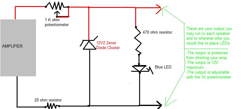
This project allows you to take those LEDs you have laying around and make them dance to your music. it's a very simple project, it takes about 1 hour at most. I'm giving these instructions in the most basic manner possible. Please let me know if you do not understand them.< br />
You can arrange them in any way you like...
Ideas:
- Across the bottom of the back seat starting at the middle and as the music gets louder it goes towards the outside of the vehical
- Project box lights up an LED, then when music gets louder, the rear speakers light up, and then the front at loudest volume
- Put them in your shifter surround's hex nuts for a little light show.
- Mount them in a straight line next to your sterio.
- get creative on your dashboard or roof.
- you can just make it so that level 3 is the only time you'll see light
Tools[]
Tools[]
- * 1 soldering gun
- * Solder
- * Black marker
- * Red marker
- * You will also need some 20AWG or higher wire.
Parts[]

- PN = radio shack part number
- * 1 project box -optional PN 270-1801
- * 1 circuit board PN 276-148
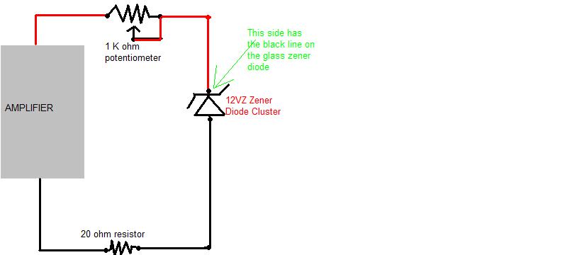
- * 2 packages of 12Vz Zener diodes (4 diodes) PN 276-563
- * 1 10K Ohm potentiometer PN 271-343
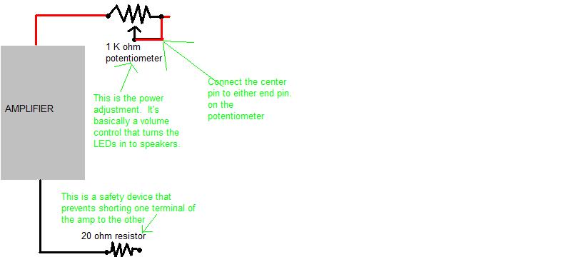
- * 1 1K Ohm potentiometer PN 271-342
- * 1 package of 10 Ohm 1W resistors PN 271-151
Selecting LEDs[]
- This stuff you can go as crazy or as light as you want. These are calculated values, find one around that size.
- * 20 or so BLUE LEDs
- * 470 ohm 1/4W resistors for strings of 1 BLUE LED
- * 280 ohm 1/4W resistors for strings of 2 BLUE LEDs
- * 120 ohm 1/4W resistors for strings of 3 BLUE LEDs
NOTE: resistance values will be different for different colored LEDs, these are for blue leds. You can go up to 6 LEDs if you choose red LEDs instead of blue, but you will need different resistors.
Instructions[]
Building the Controller[]
So we start the project by placing components on the board and soldering them in place. you do not need a board, but it tidys it up.
Have a friend read this to you as you look at the pictures below. it will make sence soon enough
- Shave the board at this point on the edges to make it small enough to fit inside the box flat.
- Set board on your work surface so the metal portions are facing downwards.
- Mark your hot and return lines.
- Draw across the top of the board, RED
- Draw across the bottom of the board Black
- Solder wires on top of board
- Tin and solder a red wire near the red line on left side
- Tin and solder a black wire near the black line
- Solder components on board.
- Place a 10 ohm resistor lengthwise along the black line with one lead next to the black wire and solder in place. try to keep it small as possible.
- Solder reistor lead to black wire
- Place 4 zener diodes next to each other starting at the free edge of the resistor from black line on board to red line on board, with the line on the zener pointing towards the red line on the board. Solder in place.
- Connect the ends of the zeners together and connect the 10ohm resistor to the non-line side of the zeners
- Mark the 10Kohm potentiometer with a C (it will be your coarse adjustment) and place it so it's first contact is on the red line, next to the red wire and it's adjustment screw is pointing off of the board.
- NOTE: the potentiometer will be used as a rheostat. We will call the pin closest to the dial "pin 1" next to the right, pin 2, and then the far right is pin 3.
- When soldering the potentiometers, connect pins 1, 2, and red wire together
- Mark the 1K ohm potentiometer with a F (it will be your fine adjustment) and place it right next to the coarse adjust potentiometer.
- Connect pins 1 and 2 on F potentiometer and pin 3 on C potentometer together
- Connect pin 3 to the black line side of the zener diodes
- Output of circuit
- Tin and connect a red wire to the black line on the zener (red line on board)
- Tin and connect a black wire to the no line side of the zener diode.
- run a marker down the edges of these 2 wires as you have a friend hold it. they will be your "signal" wires.
Pictures[]


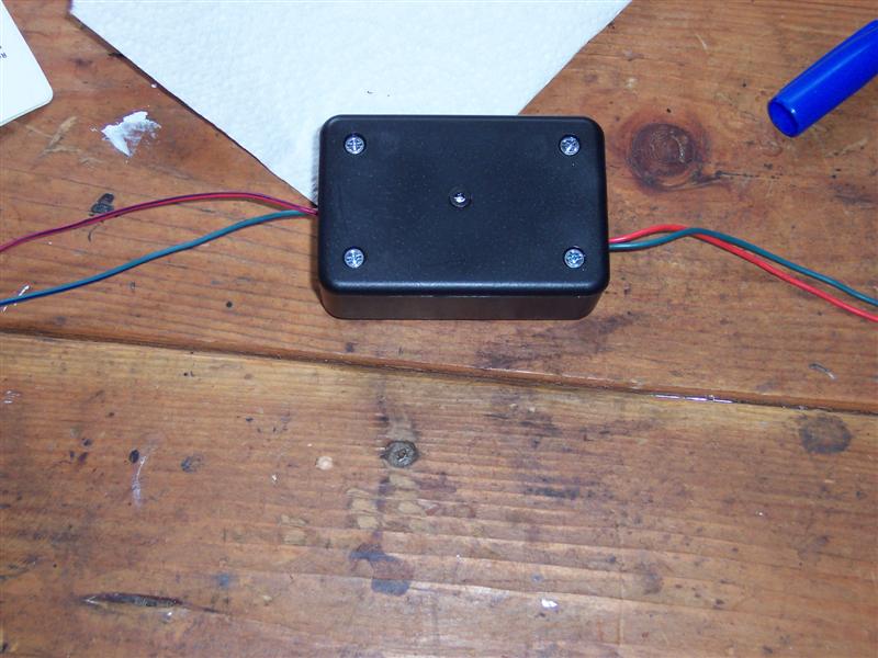
Boxing It Up[]
Ok, here's what you do with the project box.
- Stick the board in.
- Decide where you want your wires.
- Drill holes.
- Figure out how your board will lay inside.
- Drill holes for adjusting the Coarse and Fine potentiometers.
- Mount an LED with a 470 ohm resistor on the box so you can test it immediately.
Adjustments[]
- Turn the potentiometers completely counter clockwise.
- Hook up power and return wires.
- Turn the music on LOUDLY I recommend Dr Crankenstein or Bass 305, but it's your pick choose something with BASS!!!
- Slowly bring the potentiometers untll the LEDs flash brightly.
- NOTE: this system will work for a large amplifier or a small head unit, use the coarse and the fine adjust.
- NOTE: if the LEDs go to bright, you will notice blue LEDs will start to turn slightly green. turn it down!!! You will damage the LEDs quickly.
- Bring it down a few turns with the fine adjustment to compensate for when your music goes way too loud.
LEDs[]
You can now go crazy with your LEDs. Your regulator will handle about 40 LEDs in 3 led strings, about 20 in 1 LED strings Mount them in your speakers, buy custom mounts and put them wherever you'd like.
Here's how it works... with blue LEDs.
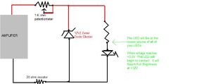
- A single LED will light at a low volume
- 2 LEDs will light at higher volumes
- 3 LEDs will light at really loud volumes
- All LEDs will reach full brightness at the loudest setting.
- 1 blue LED needs 470 ohms of resistance on a 12V circuit
- 2 blue LEDS need 280 ohms of resistance on a 12V circuit
- 3 blue LEDS need 120 ohms of resistance on a 12V circuit
You do not need to use all 3 arrangements of LEDs, but it will be more interesting if you do.
Check this DIY out for info on how to mount LEDs in speakers a rdtiburon topic
I hope this is enough. If you did it right your car should be flashing like a night club.... or maybe just dimly lighting with the music. You chose the ammount of LEDs you used.
External Links[]
For additional help see this site led.linear1.org. I do my calculations in calculator, but this could help you. The information they want is on the package. The voltage source will be 12V because of the zener diodes in this circuit.
|
If you want to add personal links, please do that on your user page (you can also write your profile there). If you have a link with great content that are needed, you can add it at here. |